


 디지털 오실로스코프 MPO-2000 시리즈
 디지털 오실로스코프 MDO-2000A 시리즈
 MDO-2000E 시리즈
 GDS-2000E 시리즈
 MSO-2000 시리즈
 GDS-1000B 시리즈
 GDS-200/300 시리즈
 GDS-2000A 시리즈
GWINSTEK
02-3439-2208 A/S 신청 및 상담
02-3439-2203/2205/2206gwinstek@gwinstek.co.kr 제품기술문의
 > GWINSTEK > 오실로스코프
 디지털 오실로스코프 GDS-3000A 시리즈
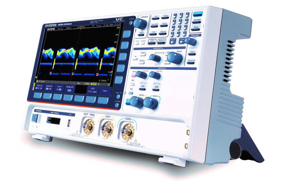

- 650MHz /350MHz 대역폭, 2채널
- 5GSa/s 리얼 타임 샘플링 속도(단일 채널); 2.5GSa/s 리얼 타임 샘플링 속도(듀얼 채널)
- 채널당 200Mpts 메모리 댑스
- 200,000 wfm/s 파형 업데이트 속도
- 10.2 인치 800*480 TFT LCD 디스플레이
- 490,000 세그먼트 메모리 및 파형 검색 기능 : 레코드 길이의 효율성을 최적화
GDS-3000A 시리즈는 GW Instek의 최신 디지털 스토리지 오실로스코프 제품으로, 주요 특징은 다음과 같습니다:
1. 주파수 대역: 최고 주파수 대역은 650MHz로, 350MHz 모델도 있습니다.
2. 메모리 댑스: 각 채널당 최대 200Mpts로, 샘플링 속도는 5GSa/s 입니다.
3. 디스플레이: 10.2" TFT LCD이며 RGB 디스플레이 출력은 각각 8비트로 측정된 신호의 강도 분포를 명확하게 분석할 수 있습니다.
4. 로직 분석기: 16채널 로직 분석기가 옵션으로 포함되어 있습니다.
5. 측정 기능: 38가지 측정항목이 제공되며, 정밀 스케일 기능이 통합되어 있습니다.
6. 파형 업데이트 속도: 200,000wfm/s로, 산발적인 이상 신호들을 쉽게 관찰할 수 있습니다.
7. 분할된 메모리: 최대 490,000개의 세그먼트를 연속적으로 캡처할 수 있으며, 마스크 기능을 통해 빠르게 검색할 수 있습니다.
8. 주파수 영역 측정: FFT 측정 기능과 듀얼 채널 스펙트럼 분석기를 제공하여 신호의 스펙트럼 특성을 관찰할 수 있습니다.
9. 전원 공급 장치 테스트: 다양한 측정 항목 옵션을 제공하여 스위칭 모드 전원 공급 장치 테스트를 수행할 수 있습니다.
10. 임의 파형 발생기: 표준 듀얼 채널 25MHz 임의 파형 발생기가 장착되어 있으며, 다양한 신호 출력을 시뮬레이션할 수 있습니다.
이러한 기능을 통해 GDS-3000A는 다양한 응용 분야에서 신호 분석 및 측정을 위한 강력한 도구로 사용될 수 있습니다.
오실로스코프를 이용하여 자기부품의 동적자기이력곡선 (B-H)곡선 만드는 방법
자속밀도(Magnetic Flux Density (B))와 자계강도(Magnetic Field Strength (H))를 생성하기 위한 디지털 오실로스코프 사용법을 상술하며,
정적(정현파) 자기이력곡선(B-H곡선)측정과 동적 여기원(Excitation Source)측정 사이의 차이점에 대하여 설명합니다.
인덕터와 변압기는 전원회로내에서 공통적인 자기 부품이며, 에너지 저장과 에너지 변환의 역할을 수행합니다.
자기부품들은 권선(Winding)과 자기 철심(Magnetic Core)으로 구성되어 있습니다. 투자율(Magnetic Permeability(μ)), 온도특성,
주파수 특성과 자성체(Magnetic Material)의 구조는 자기부품의 상세사항을 결정합니다.


잔류자기(Magnetic Remanence
(Mr)) 또는 유지력(Remanence (Retentivity))
외부 자계(Magnetic Field)의 세기가 감소할 때, 자기 쌍극자의 세기(Magnetic
Dipole Strength) 역시 약해질 것입니다.
외부 자계(Magnetic Field)가 0으로 떨어질 때, 자성체의 자기 쌍극자의 세기(Magnetic Dipole)는 0이 되지 않을 것이고 약간의 자화를 유지하고 있을 것입니다.
외부 자계(Magnetic Field)가 반대방향으로 증가할 때, 잔류 자화강도(Magnetization
Intensity (M))는 다시 감소합니다.
오직 외부 자계(Magnetic Field)가 반대 방향으로 어느 정도 센 상태에 도달할 때 남아있는 자기 쌍극자가 사라지게 할 수 있습니다.
(그렇습니다, 자화 강도가 0이 됩니다.) 자계(Magnetic Field)의 강도가 반대 방향으로 적용되면 보자성(Coercivity), Hc 라고 부릅니다.
외부 자계(Magnetic Field)가 반대 방향으로 계속 증가한다면, 자성체는 0이 아닌 비잔류 자화강도(Magnetization Intensity) M을 만들어낼 것입니다.
외부 자계(Magnetic Field)의 강도와 방향이 변할 때, 자성체(Magnetic Material)의 자기 쌍극자(Magnetic Dipole)는 특정하게 변할 것이고,
이것을 자기이력곡선(히스테리시스 곡선 또는 B-H곡선)이라 부릅니다.
정적(정현파)이력곡선(B-H곡선)측정과 동적 여기원(Excitation Source)측정의 차이점
정적인 측정은 여기원(Excitation Source)과 같이 고정된 주파수를 사용합니다.
자화부품(Magnetic Components)의 설계목적은 최대치 전류의 상황에서도 정상적으로 동작하는 것이고, 그것은 자기 포화가 일어나지 않음을 의미합니다.
실제 최대 여기전류(Excitation Current)는 실제동작상태를 얻기 위해서 실제적 동적 전류파형에서 측정되어야 합니다. 이 실제 동작상태는 실제온도 조건들을 포함합니다.
자성체(Magnetic Substance)는 퀴리온도(Curie Temperature)를 가지고 있습니다. 각 물질의 퀴리온도(Curie Temperature)는 다릅니다.
자성체(Magnetic Substance)가 퀴리온도(Curie Temperature)를 초과할 때, 자기 쌍극자들(Magnetic Dipoles)내부의 물질은 그들의
배열로부터 이탈하여 나올 충분한 에너지를 얻을 것이며, 순서대로 배열된 방향에서 무질서한 배열로 변하고 자성은 사라질 것입니다.
아래의 화면들은 MOSFET의 여러가지 스위칭 사이클들의 측정 결과들을 보여줍니다.
GDS-3000A의 자기이력곡선(B-H곡선)측정 결과들은 L사 제품 WaveRunner 8108HD의 시험 결과에 근접합니다

<GWISNTEK GDS-3000A의 자기이력곡선(B-H곡선)과 L사 제품 : WaveRunner 8108HD 비교>


주요 사양 및 기능
|
주요 사양 l 650MHz /350MHz 대역폭, 2채널 l 5GSa/s 리얼 타임 샘플링 속도(단일
채널); 2.5GSa/s 리얼 타임 샘플링 속도(듀얼 채널) l 채널당
200Mpts 메모리 댑스 l 200,000 wfm/s 파형 업데이트
속도 l 10.2 인치 800*480 TFT LCD 디스플레이 l 490,000 세그먼트 메모리 및 파형 검색 기능 : 레코드 길이의 효율성을 최적화 l 38가지 자동 측정 기능으로 다양한 측정 선택 가능 l 고분해능 획득 모드 l I2C/SPI/UART/CAN/LIN 직렬 버스
트리거 및 디코딩 기능 l 듀얼 채널 스펙트럼 분석기 (DC~2.5GHz) l 듀얼 채널 25MHz
임의 파형 발생기 l 옵션) 13세트 전력 분석 측정 l 옵션) 16채널 로직 아날라이저 (MSO) |
인터페이스 l High-speed USB device 포트, host 포트 l RS232 l LAN l VGA 출력 l Go/NoGo BNC l 켄싱턴 스타일
lock l GPIB(옵션, 공장 설치)
소프트웨어 및 드라이버 l PC 소프트웨어 (OpenWave 소프트웨어) l LabVIEW 드라이버
|
|
|
특징 |
장점 |
이점 |
|
1 |
650MHz
대역폭 |
같은 범주의 오실로스코프의 대부분은 500MHz의 가장
높은 주파수 대역폭만을 제공합니다. |
50ohm 임피던스
매칭에서 650MHz 대역폭을 제공합니다. 500MHz 대역폭의 오실로스코프와 비교하면 사용자는
DUT의 주파수 범위를 늘릴
수 있습니다 |
|
2 |
200M/CH 메모리 댑스 |
동일한 범주의 오실로스코프에서 채널당 가장 긴
메모리 댑스를 제공합니다.
긴 메모리는 저속 수평
레벨 설정에서 높은 샘플링
속도를 유지할 수 있습니다.
장기간의 이상 현상
검색을 위한 시스템의
응용에 매우 적합하며
문제의 심층 분석에
매우 유용합니다.. |
메모리 댑스가 길수록 사용자는 파형 세부
사항을 관찰하고 분석할 수
있습니다. |
|
3 |
최대200,000
wfm/s 파형 업데이트 속도 |
더 빠른 업데이트
속도는 비정상적이고 산발적인 신호의 수집 또는
제품 디버깅에 도움이
됩니다. |
파형 변경
세부 사항을 더 짧은
시간에 정확하게 캡처하여 제품
문제의 근본 원인을
빠르게 이해할 수 있습니다. |
|
4 |
490,000 세그먼트 메모리 |
분할된 메모리는 최대 490,000개의 세그먼트로
나눌 수 있습니다. 의미 있는 신호
파형을 고속으로 그리고 지속적으로 캡처할
수 있습니다. |
트리거 조건을 설정하면 오랫동안
변하지 않은 파형은
건너뛰고 의미 있는
파형만 기록할 수 있어
사용자가 문제를 빠르게 찾을
수 있다. 또한 다수의
캡처된 신호가 목표 범위를
벗어났는지 여부를 결정하기 위해
Mask 기능과 함께 사용할
수 있습니다. 신호 분석
및 디버깅을 위한 좋은
도구입니다. |
|
5 |
고분해능 모드 |
파형 노이즈를 효과적으로 줄일
수 있습니다. |
고분해능 모드는 파형 노이즈를
줄여 원래 파형을
더 쉽게 관찰하고
측정할 수 있으며
파형의 수직 분해능을
개선하여 더 높은
측정 정확도를 얻을 수
있습니다. |
|
6 |
커서 마크, 표시기 |
커서 마크, 표시기 라벨링 기능
통합 |
커서 측정 범위와
측정 포인트의 데이터를 한눈에
볼 수 있습니다. |
|
7 |
미세 스케일 |
더 미세한
수직 범위 제공 |
수직 전압 스케일
조정 외에도 미세 스케일
조정을 통해 측정
신호가 전체 스케일
진폭에 도달하여 오실로스코프의 수직 측정
정확도가 향상됩니다. |
|
8 |
듀얼 채널 스펙트럼
분석기 및 스펙트로그램
기능 |
듀얼 채널 스펙트럼
분석 기능 제공 |
스펙트럼 분석기와 유사한 측정
및 작동 인터페이스가
장착되어 듀얼 채널 주파수
영역 분석 및
비교를 수행할 수 있습니다.
2.5GHz의 주파수 영역 테스트
범위는 저주파 원격 컨트롤러,
NFC, RFID 및 기타 애플리케이션의
테스트 및 분석에
유용합니다. |
|
9 |
13 세트 전력 분석
측정
|
다양한 전력
측정 기능(옵션) |
풍부한 전원 공급
장치 테스트 항목은 스위칭 전원 공급 장치 DUT에 대한AC 입력 라인
분석 / DC출력 분석등을 만족시킬 수 있습니다. |
|
10 |
전류 프로브용
전원 공급 장치 |
전류 프로브 전원 공급
장치를 구입하기 위한 예산을
절약합니다. 편리한 고주파 전류
테스트를 제공합니다. |
사용자가 GCP-530 또는 GCP-1030 전류 프로브를
사용해야 하는 경우 전용 전원
공급 장치를 구입할 필요가
없습니다.
GDS-3000A는 오실로스코프 측면의 프로브에
필요한 전원 출력을
제공합니다. 이 디자인을
통해 사용자는 비용을 절감하고
외부로 운반하는 부담을 줄일
수 있습니다. |
|
11. |
듀얼 채널 임의
파형 발생기 |
듀얼 채널 25MHz 다기능 신호
발생기 표준 제공 |
신호 시뮬레이션 요구 사항이
있는 경우,
사용자는 다른 신호
발생기를 준비할 필요가 없습니다.
내장된 듀얼 채널 AWG의 신호
출력을 직접할 수
있습니다. |
GDS-3000A 사양
The specifications apply when the GDS-3000A series is powered on
for at
least 30 minutes under 20°C~30
|
GDS-3352A |
Channels |
2 + Ext |
|
|
Bandwidth |
DC ~ 350MHz (–3dB) @50Ω/1MΩ input impedance |
|
|
Rise Time |
1ns (calculated) |
|
|
Bandwidth Limit |
20MHz/100MHz/200MHz* |
|
GDS-3652A |
Channels |
2 + Ext |
|
|
Bandwidth |
DC ~ 650MHz
(–3dB) @ 50Ω input impedance DC ~ 500MHz
(–3dB) @1MΩ input impedance |
|
|
Rise Time |
535ps
(calculated) |
|
|
Bandwidth
Limit |
20MHz/100MHz/200MHz/300MHz* |
|
* The
tolerance of bandwidth limit is ±10%.
|
||
|
Vertical
Sensitivity |
Resolution |
8 bits (Max.12 bits with Hi
Res) For
1MΩ input impedance: 1mV*~10V/div For
50Ω input impedance: 1mV*~1V/div |
|
Input
Coupling |
AC, DC, GND |
|
|
Input Impedance |
1MΩ// 22pF approx. |
|
|
DC Gain
Accuracy |
1mV: ±5%
full scale |
|
|
Polarity |
Normal & Invert |
|
|
Maximum
Input Voltage |
For 1MΩ input impedance: 300Vrms, CAT
II For 50Ω input impedance: 5Vrms max. |
|
|
Offset Position Range |
For
1MΩ input impedance: 1mV/div ~ 20mV/div :±1V; 50mV/div ~ 500mV/div: ±10V 1V/div ~ 5V/div : ±100V; 10V/div : ±1000V For
50Ω input impedance: 1mV/div ~ 50mV/div:±1V; 100mV/div ~ 1V/div : ±10V |
|
|
Waveform
Signal Process |
+, -, ×, ÷,
FFT, User Defined Expression FFT: Spectral
magnitude. Set FFT Vertical Scale to Linear RMS or dBV RMS, and FFT Window to
Rectangular, Hamming, Hanning or Blackman. |
|
|
Trigger |
Source |
CH1, CH2, Line, EXT |
|
Trigger
Mode |
Auto (supports
Roll Mode for 100ms/div and slower), Normal, Single |
|
|
Trigger Type |
Edge, Pulse Width(Glitch), Video, Pulse Runt, Rise
& Fall(Slope), Timeout, Alternate, Event-Delay(1~65535 events),
Time-Delay(Duration, 4ns~10s), Bus (UART, I2C,
SPI, CAN, LIN) |
|
|
Holdoff
range |
4ns to 10s |
|
|
Coupling |
AC, DC, LF rej., HF rej., Noise rej. |
|
|
Sensitivity |
1div |
|
External
Trigger |
Range |
±20V |
|
Sensitivity |
DC ~ 100MHz Approx.
100mV |
|
|
Input Impedance |
1MΩ±3%~22pF |
|
|
*:
The bandwidth is limited to 20MHz at 1mV/div and 2mV/div. |
||
|
Horizontal |
Time base Range |
1ns/div ~ 1000s/div (1-2-5 increments) |
|
Pre-trigger |
10 div maximum |
|
|
Post-trigger |
10,000,000 div maximum. |
|
|
Time base Accuracy |
±5 ppm, about
±2ppm
increase in error per year |
|
|
Signal Acquisition |
Real
Time Sample Rate |
5GSa/s one
channel; 2.5GSa/s dual
channels
|
|
Record Length |
Max. 200Mpts /CH |
|
|
Acquisition Mode |
Normal, Average, High
Resolution, Peak Detect,
Single |
|
|
|
Peak
Detection |
400ps (typical) |
|
|
Average |
Selectable from 2 to 256 |
|
|
Number
of Segments |
1
to 490,000 maximum |
|
X-Y Mode |
X-Axis
Input |
Channel 1 |
|
Y-Axis Input |
Channel 2 |
|
|
Phase
Shift |
±3° at 100kHz |
|
Cursors and Measurement |
Cursors |
Amplitude, Time, Gating
available; Unit: Seconds(s), Hz (1/s),
Phase (degree), Ratio (%). |
|
Automatic Measurement |
38 sets
with indicator: Pk-Pk, Max, Min, Amplitude, High, Low, Mean, Cycle Mean, RMS, Cycle
RMS, Area, Cycle Area, ROVShoot, FOVShoot, RPREShoot, FPREShoot, Frequency,
Period, RiseTime, FallTime, +Width, -Width, Duty Cycle, +Pulses, -Pulses,
+Edges, -Edges, %Flicker, Flicker Idx ,FRR, FRF, FFR, FFF, LRR, LRF, LFR,
LFF, Phase. |
|
|
Cursors measurement |
Voltage difference
between cursors(∆V) Time difference between
cursors(∆T) |
|
|
Auto counter |
6 digits, range from 2Hz
minimum to the rated bandwidth |
|
|
Control
Panel Function |
Autoset |
Single-button, automatic
setup of all channels for vertical, horizontal and trigger systems, with “Undo Autoset”,
“Fit Screen”/ “AC Priority” mode, and “Fine Scale” functions. |
|
Save Setup |
20 sets |
|
|
Save Waveform |
20 sets |
|
|
|
Save Reference
Waveform |
4
sets |
|
Power Measurement (Option) |
Power Quality, Harmonics,
Ripple, In-rush current, Switching Loss, Modulation, SOA, Transient,
Efficiency, B-H curve, Control Loop Response, PSRR, Turn On/Off |
|
|
AWG |
General |
|
|
Channels |
2 |
|
|
Sample Rate |
200MSa/s |
|
|
Vertical Resolution |
14 bits |
|
|
Max. Frequency |
25 MHz |
|
|
Waveforms |
Sine, Square, Pulse, Ramp, DC, Noise Sinc, Gaussian, Lorentz, Exponential Rise,
Exponential Fall, Haversine, Cardiac |
|
|
Output Range |
20 mVpp to 5 Vpp, HighZ; 10 mVpp to 2.5 Vpp, 50Ω |
|
|
Output Resolution |
1mV |
|
|
Output Accuracy |
2% (1 kHz) |
|
|
Offset Range |
±2.5 V, HighZ; ±1.25 V, 50 Ω |
|
|
Offset Resolution |
1mV |
|
|
Sine |
|
|
|
Frequency Range |
100 mHz to 25 MHz |
|
|
Flatness |
±0.5 dB < 15MHz; ±1dB 15MHz~25MHz |
|
|
Harmonic Distortion |
-40 dBc |
|
|
Stray (Non-harmonic) |
-40 dBc |
|
|
Total Harmonic Distortion |
1% |
|
|
S/N Ratio |
40 dB |
|
|
Square/Pulse |
|
|
|
Frequency Range |
Square: 100 mHz to 15 MHz |
|
|
Rise/Fall Time |
< 15ns |
|
|
Overshoot |
< 3 % |
|
|
Duty Cycle |
Square: 50% Pulse: 0.4% to 99.6% |
|
|
Min. Pulse Width |
30ns |
|
|
Jitter |
500 ps |
|
|
Ramp |
|
|
|
Frequency Range |
100 mHz to 1MHz |
|
|
Linearity |
1% |
|
|
Symmetry |
0 to 100% |
|
|
Spectrum Analyzer |
Frequency Range |
DC~2.5GHz Max, dual channel with spectrogram (based on Advanced
FFT). Notice: Frequency which exceeds analog front end bandwidth is
uncalibrated |
|
Span |
1kHz~2.5GHz (Max.) |
|
|
Resolution Bandwidth |
1Hz~2.5MHz (Max.) |
|
|
Reference Level |
-80dBm to +40dBm in
steps of 5dBm |
|
|
Vertical Units |
dBV RMS; Linear RMS; dBm |
|
|
Vertical Position |
-12divs to +12divs |
|
|
Vertical Scale |
1dB/div to 20dB/div in a 1-2-5 Sequence |
|
|
Displayed Average
Noise Level |
1V/div ß -40dBm, Avg :16 100mV/div ß -60dBm, Avg :16 10mV/div ß -80dBm, Avg :16 |
|
|
Spurious Response |
2nd harmonic distortion < 35dBc 3rd harmonic distortion < 40dBc |
|
|
Frequency Domain Trace
Types |
Normal; Max Hold; Min
Hold; Average (2 ~ 256) |
|
|
Detection Methods |
Sample; +Peak; -Peak; Average |
|
|
FFT Windows |
FFT Factor: |
|
|
Logic Analyzer (Option) |
Sample Rate |
1GSa/s |
|
Bandwidth |
200MHz |
|
|
Record Length |
Per Channel |
|
|
Input Channels |
16 Digital (D15 - D0) |
|
|
Trigger type |
Edge, Pattern, Pulse Width, Serial bus (I |
|
|
Thresholds Quad |
Settable thresholds
for: D0-D3, D4-D7, D8-11,
D12-15 |
|
|
Threshold selections |
TTL, CMOS(5V,3.3V,2.5V), ECL, PECL,0V ,User Defined |
|
|
|
±5V |
|
|
Maximum Input Voltage |
±40 V |
|
|
Minimum Voltage Swing |
±250 mV |
|
|
Vertical Resolution |
1 bit |
|
|
Frequency Response Analyzer |
Frequency Range |
20Hz to 25MHz |
|
Input and Output Sources |
Channel 1 ~ 2 |
|
|
Number of Test Points |
10, 15, 30, 45, 90 points per decade selectable
for logarithm scale; 2 ~
1000 points selectable
for linear scale |
|
|
Dynamic Range |
> 80dB (typical) |
|
|
Test Amplitude |
10mVpp to 2.5Vpp into 50Ω, 20mVpp to 5Vpp into High-Z, Fixed test amplitude or custom amplitude for each
decade. |
|
|
Test Results |
Logarithmic or
linear overlaid gain and phase plot, may also overlay with reference plots for cross comparison.
Test results saved in csv format for offline
analysis. |
|
|
Manual Measurements |
Tracking gain and phase markers |
|
|
Plot
Scaling |
Auto-scaled
during test |
|
|
Display |
TFT LCD Type |
10.2" TFT LCD WVGA color display |
|
Display Resolution |
800 horizontal × 480
vertical pixels (WVGA) |
|
|
Interpolation |
Sin(x)/x |
|
|
Waveform Display |
Dots, vectors,
variable persistence (16ms~4s), infinite persistence, gray or color waveforms. |
|
|
Waveform Update Rate |
200,000 waveforms per second, maximum |
|
|
Display Graticule |
8 x 10 divisions |
|
|
Display Mode |
YT, XY |
|
Interface |
USB Port |
USB 2.0 High-speed host
port X1, USB High-speed 2.0 device port X1 |
|
Ethernet Port (LAN) |
RJ-45 connector X1, 10/100Mbps with HP Auto-MDIX |
|
|
Go-NoGo BNC |
5V Max/10mA open
collector output X1 |
|
|
|
Power Supply Receptacles |
±12V / 600mA for current probe use. Two sets of power supply receptacles for
2CH models; |
|
|
RS232C |
DB-9
male connector X1 |
|
|
VGA Video Port |
DB-15 female connector X1, monitor output
for display on VGA monitor |
|
|
Optional
GPIB Module |
Fully
programmable with IEEE488-2 compliance |
|
|
Kensington Style Lock |
Rear-panel security slot connects to standard Kensington-style lock. |
|
Miscellaneous |
Multi-language menu |
Available |
|
Operation Environment |
Temperature: 0°C to 50°C. Relative Humidity ≤ 80% at 40°C or below; |
|
|
On-screen help |
Available |
|
|
Time clock |
Time and Date, Provide the Date/Time for saved data |
|
|
Internal
Flash Disk |
800M bytes Single-Level Cell flash memory |
|
|
Installed APP |
Go/NoGo, DVM, DataLog, Digital Filter,
Frequency Response Analyzer, Mask, Mount Remote Disk, Demo |
|
|
|
User
Define Key |
User
can select one of the several different preset functions as shortcut key. |
|
|
Line
Voltage range |
AC
100V ~ 240V, 50Hz ~ 60Hz, auto selection. power consumption:100W |
|
|
Weight |
Approx.
4.6kg |
|
|
Dimensions |
420mm(W)X 253mm(H)X 113.8mm(D) |
|
|
|
|
기본 액세서리 | |
전원 코드x 1 , 제품 보증서 | |
GTP-351R GTP-501R | GDS-3352A / GDS-3354A : 350MHz 10:1 측정 프로브 (채널수와 동일하게 제공) GDS-3652A / GDS-3654A : 500MHz 10:1 측정 프로브 (채널수와 동일하게 제공) |
|
|
옵션 액세서리 | |
DS3A-16LA | 16채널 로직 분석기 |
DS3A-GPIB | GPIB 인터페이스 옵션 (Factory INSTALL) |
GTL-248 GTP-033A GCP-300 GCP-500 GCP-1000 GCP-530 GCP-1030 GDP-025 GDP-050 GDP-100 GKT-100 GRA-443 GTL-232 | GPIB 케이블 , Double shield, 2000 mm 35MHz 1:1 Passive probe 300kHz / 200A 전류 프로브 500kHz / 150A 전류 프로브 1MHz / 70A 전류 프로브 50MHz / 30A 전류 프로브 100MHz / 30A 전류 프로브 25MHz 고전압 차동 프로브 50MHz 고전압 차동 프로브 100MHz 고전압 차동 프로브 Deskew fixture 랙 마운트 키트 RS-232C 케이블 , 9-pin female to 9-pin female, Null modem for computer |
주문 정보 | ||
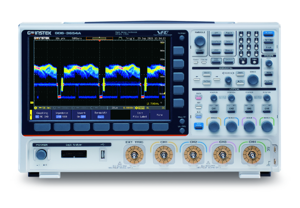
GDS-3352A | 350MHz, 2-channel, Digital Storage Oscilloscope | 견적문의 |
GDS-3354A | 350MHz, 4-channel, Digital Storage Oscilloscope | 견적문의 |
GDS-3652A GDS-3654A | 650MHz, 2-channel, Digital Storage Oscilloscope 650MHz, 4-channel, Digital Storage Oscilloscope | 견적문의 견적문의 |