
1. 시뮬레이터 모드
DUT가 변동 현상에 의해 겪는 영향을 평가하기 위해 엔지니어가 전원 장애, 전압 상승 및 전압 하락 등과 같은 다양한 모의 입력 임시 파형을 빠르게 생성할 수 있습니다. 예를 들어, 커패시터 내구성 테스트에 사용됩니다.

 > >
> > 
• 4.3인치 TFT-LCD • 출력 용량:
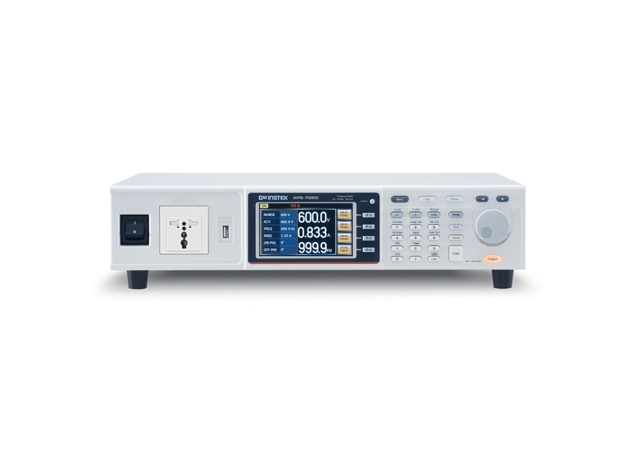
- APS-7050(500VA, 310Vrms, 4.2Arms)
- APS-7100 (1000VA, 310Vrms, 8.4Arms)
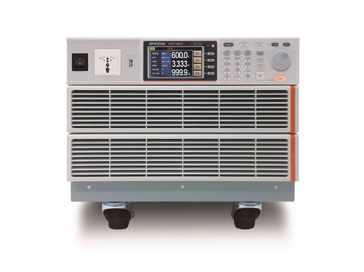
- APS-7200(2000VA, 310Vrms, 16.8Arms)
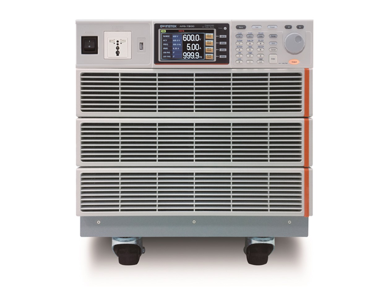
- APS-7300 (3000VA, 310Vrms, 25.2Arms)
옵션에 따른 출력 증가 (0-600Vrms/45999.9Hz) • 낮은 리플 및 노이즈 • 측정 및 테스트 기능: 전압(VOLT), 전류(CURR), 전력(PWR), 허용 전력(SVA), 피크 전류(IPK), 피크 전류 홀드(IPKH), 주파수(FREQ), 역률(PF), 복합 역률(CF) • 2mA ~ 35A의 소형 AC 전류 측정 지원, 최소 해상도 0.01mA(APS-7050 및 APS-7100) • 역전류 경보 기능 • 10 세트의 순서 기능으로 출력 파형 편집
• 10 세트의 순간 전원 공급량 신속 시뮬레이션 모드
• 10 세트의 측정 순서 정의를 위한 프로그램 모드
패널 메모리 기능 10 세트
• 전원이 켜질 때 시퀀스, 시뮬레이트, 프로그램 모드 및 출력 기능의 자동 실행 • 표준 인터페이스: LAN, USB 호스트, USB 장치 (APS-7200 및 APS-7300 모델 전용)
DUT가 변동 현상에 의해 겪는 영향을 평가하기 위해 엔지니어가 전원 장애, 전압 상승 및 전압 하락 등과 같은 다양한 모의 입력 임시 파형을 빠르게 생성할 수 있습니다. 예를 들어, 커패시터 내구성 테스트에 사용됩니다.
1. 사용자가 천장 및 바닥 사양을 설정하여 측정이 완료된 후 PASS/FAIL 결과를 생성할 수 있습니다.
2. 각 테스트 절차에 대한 테스트 결과를 표시하거나 마지막 결과만 표시할 수도 있습니다.
3. 프로그램 모드는 10개의 세트가 있으며 각 세트에는 50개의 메모리 세트가 있습니다.
4. 각 메모리에는 9단계가 포함되어 있습니다.
5. 각 프로그램은 메모리 순서, 사용자가 정의한 루프 또는 지정된 단계에 따라 실행됩니다.

Program Mode
| 03 | 함수파형 (ARB ) 모드 |
|
| |

DUT에 대한 입력 전원으로 정상 전압에 Surge / DIP전압을 겹쳐서 사용자가 Surge / DIP 상황을 시뮬레이션하고 DUT 특성을 평가할 수 있습니다.

Dip

Surge
Surge
| 05 | T Ipeak, 홀드 기능 |
T, Ipk 홀딩은 출력 Ipeak 값 및 최대 값을 측정 후 지연 시간 (1ms~60초)을 설정하고 최대 값을 검색합니다. 측정된 값이 원래 값보다 크면 업데이트됩니다. Ipk 보유는 보통 오실로스코프 및 전류 프로브로 수행되는 장비 전원을 켤 때 순간적인 동습 전류를 측정하기 위해 사용됩니다. T, Ipk 홀딩 지연 시간 설정은 순차적으로 활성화된 DUT의 Inrush 전류를 측정하는 데 적용될 수 있습니다.

Ipeak Measurement
| 06 | 제어 패널 특 |
 |
|
Standard Mode
|
|

|
기본 액세서리 | |
|
사용 설명서 CD x 1, 전원 코드 x 1, 단자 덮개 세트 x 1, 테스트 리드 GTL-123 x 1 | |
|
옵션 액세서리 | |
|
APS-001 |
GPIB 인터페이스카드 |
|
APS-002 |
RS-232/USB CDC 인터페이스 카드 |
|
APS-003 |
전압 범위 확장 : 0~600Vrms |
|
APS-004 |
주파수 범위 확장 : 45~999.9Hz |
|
APS-007 |
RS-232 인터페이스 카드 (APS-7200, APS-7300) |
|
GRA-423 |
APS-7050, APS-7100 랙 마운트 키트 |
|
GRA-429 |
APS-7200 랙 마운트 키트 |
|
GRA-430 |
APS-7300 랙 마운트 키트 |
|
주문 정보 | ||
|
APS-7050 |
1채널 프로그래머블 리니어 AC 전원 공급기 (500VA) |
견적문의 |
|
APS-7100 |
1채널 프로그래머블 리니어 AC 전원 공급기 (1kVA) |
견적문의 |
|
APS-7200 |
1채널 프로그래머블 리니어 AC 전원 공급기 (2kVA) |
견적문의 |
|
APS-7300 |
1채널 프로그래머블 리니어 AC 전원 공급기 (3kVA) |
견적문의 |
|
옵션 액세서리 | ||
|
APS-001 |
GPIB 인터페이스카드 |
견적문의 |
|
APS-002 |
RS-232/USB CDC 인터페이스 카드 |
견적문의 |
|
APS-003 |
전압 범위 확장 : 0~600Vrms |
견적문의 |
|
APS-004 |
주파수 범위 확장 : 45~999.9Hz |
견적문의 |
|
APS-007 |
RS-232 인터페이스 카드 (APS-7200, APS-7300) |
견적문의 |
|
GRA-423 |
APS-7050, APS-7100 랙 마운트 키트 |
견적문의 |
|
GRA-429 |
APS-7200 랙 마운트 키트 |
견적문의 |
|
GRA-430 |
APS-7300 랙 마운트 키트 |
견적문의 |
|
상기 가격은 부가세 별도 가격입니다. | ||
