
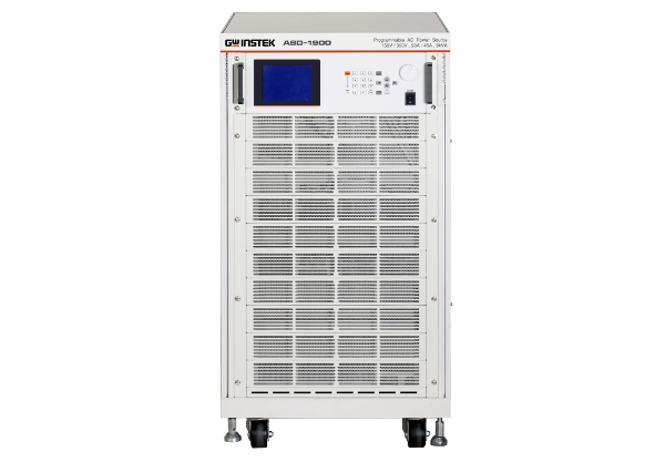
 AC전원공급기 ASD-1900
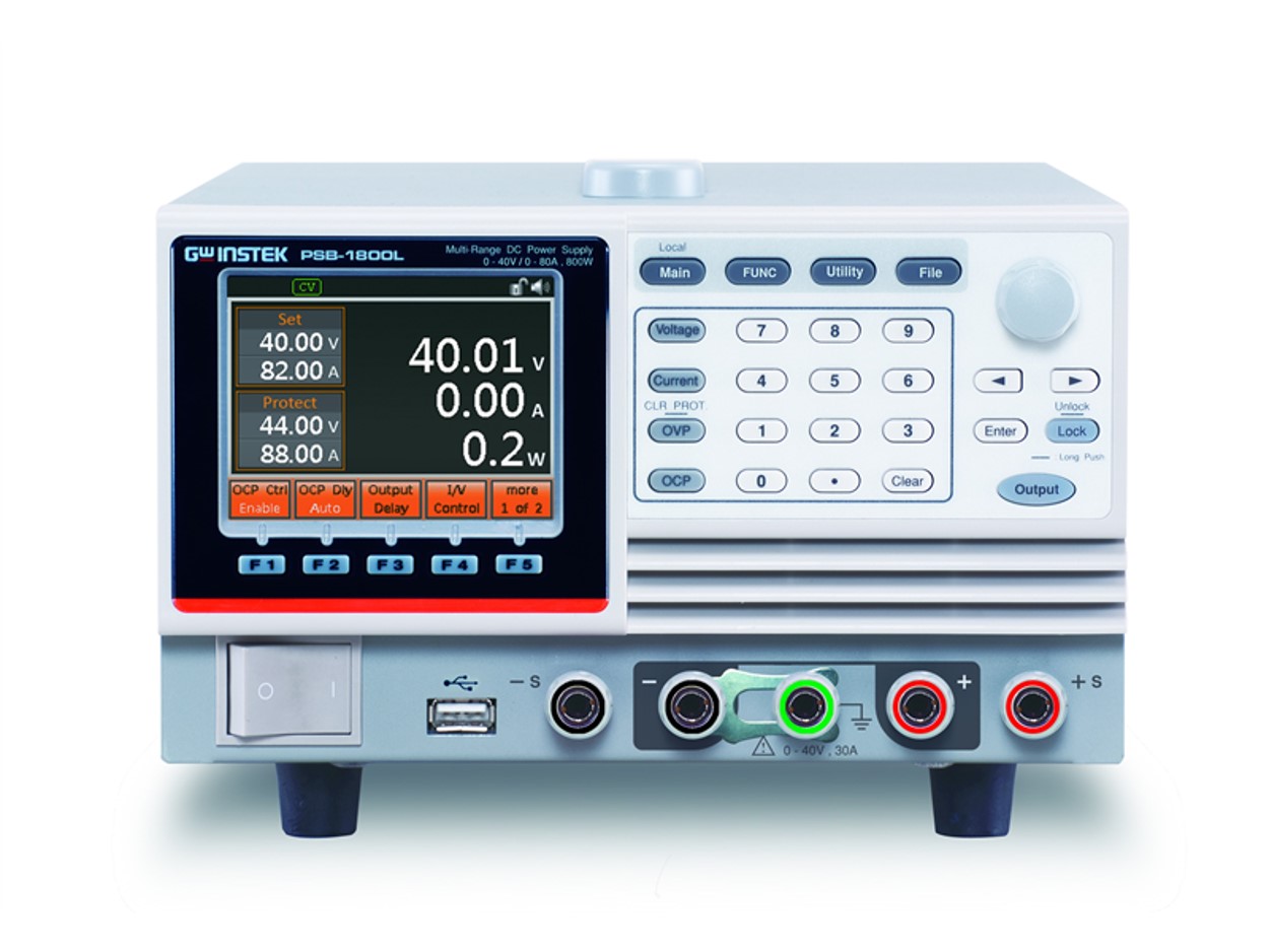 PSB-1000 시리즈
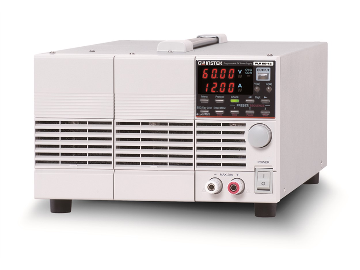 PLR 시리즈
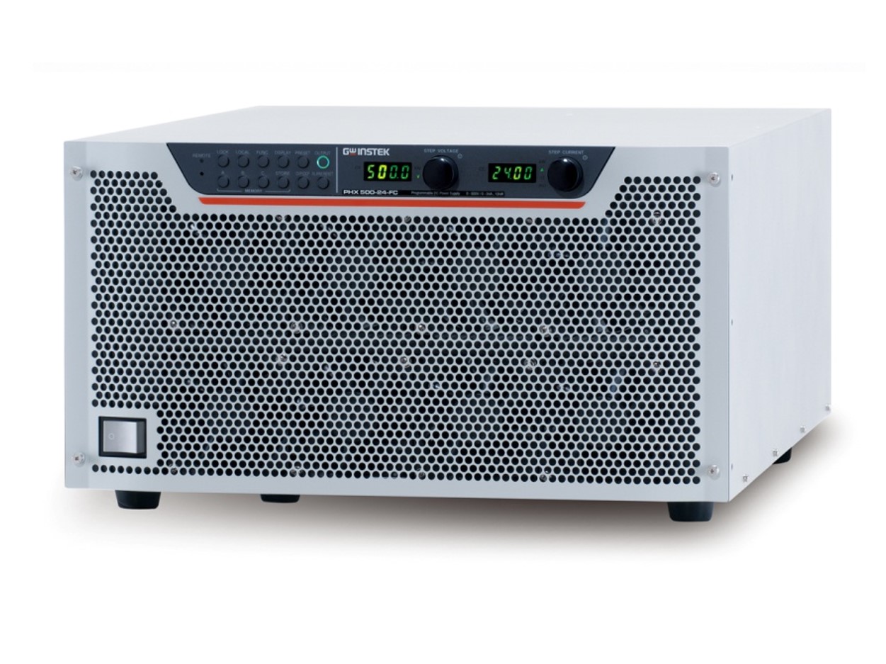 PHX 시리즈 (PHX-A 시리즈로 모델 변경)
 GDS-1000A-U 시리즈
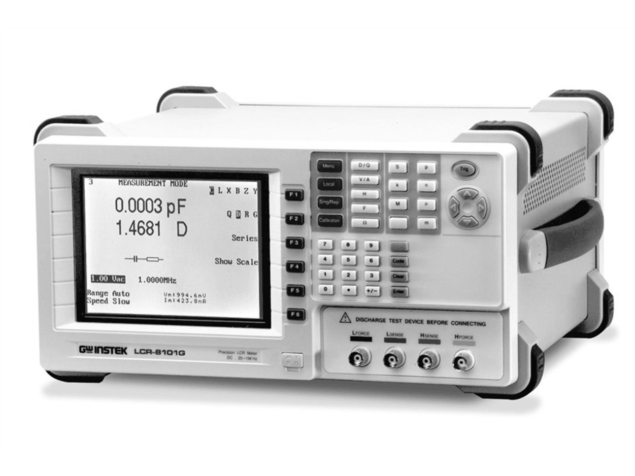 LCR-8000G 시리즈 (단종)
 GKP-2302 (단종)
 APS-1102A (단종)
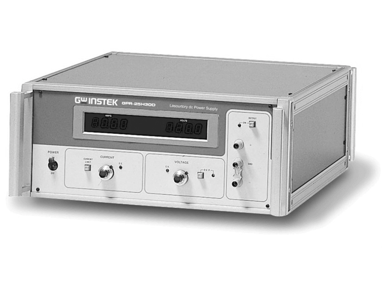 GPR-U 시리즈 (단종)
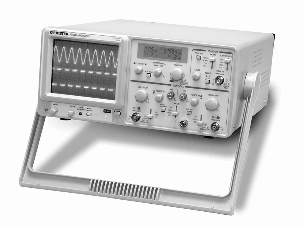 GOS-630FC (단종)
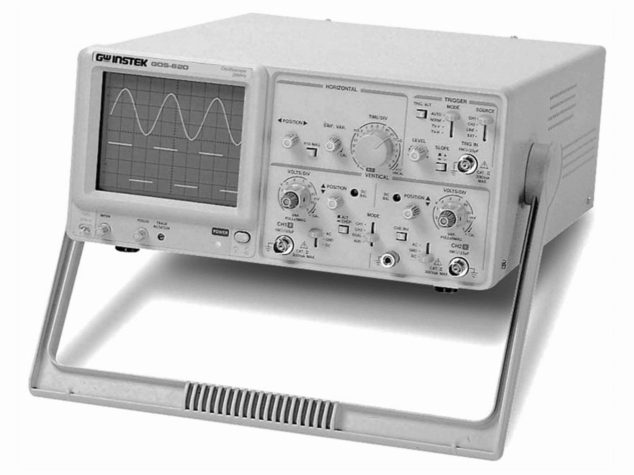 GOS-620 (단종)
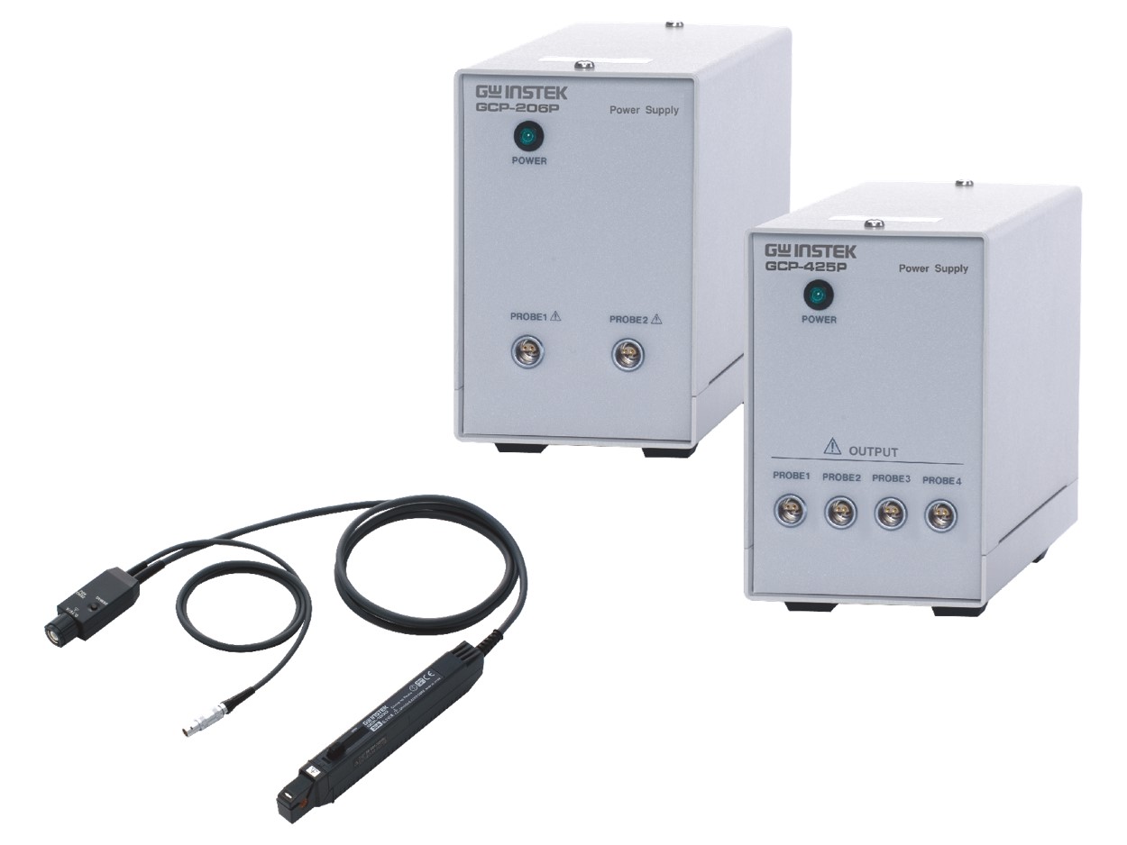 GCP-530/1030
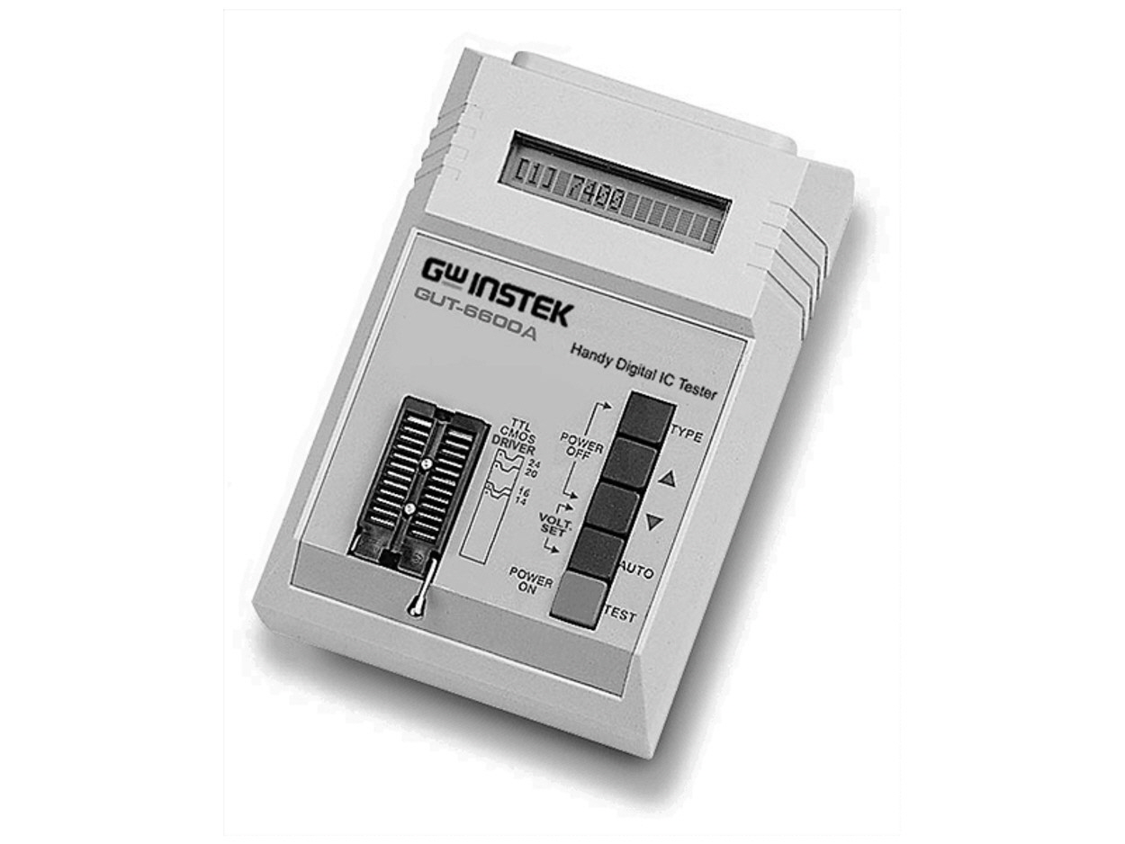 GUT-6600A (단종)
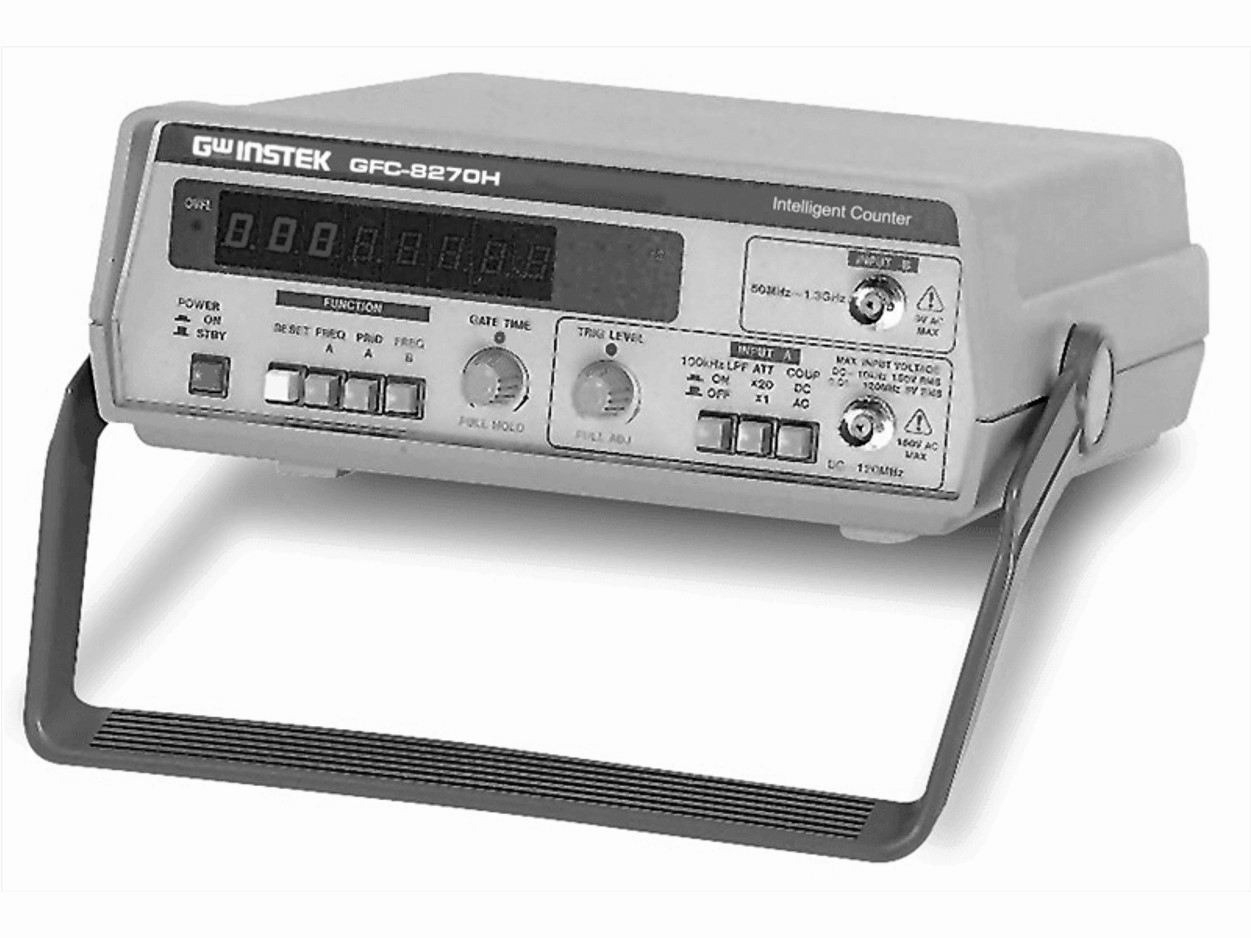 GFC-8270H/8131H (단종)
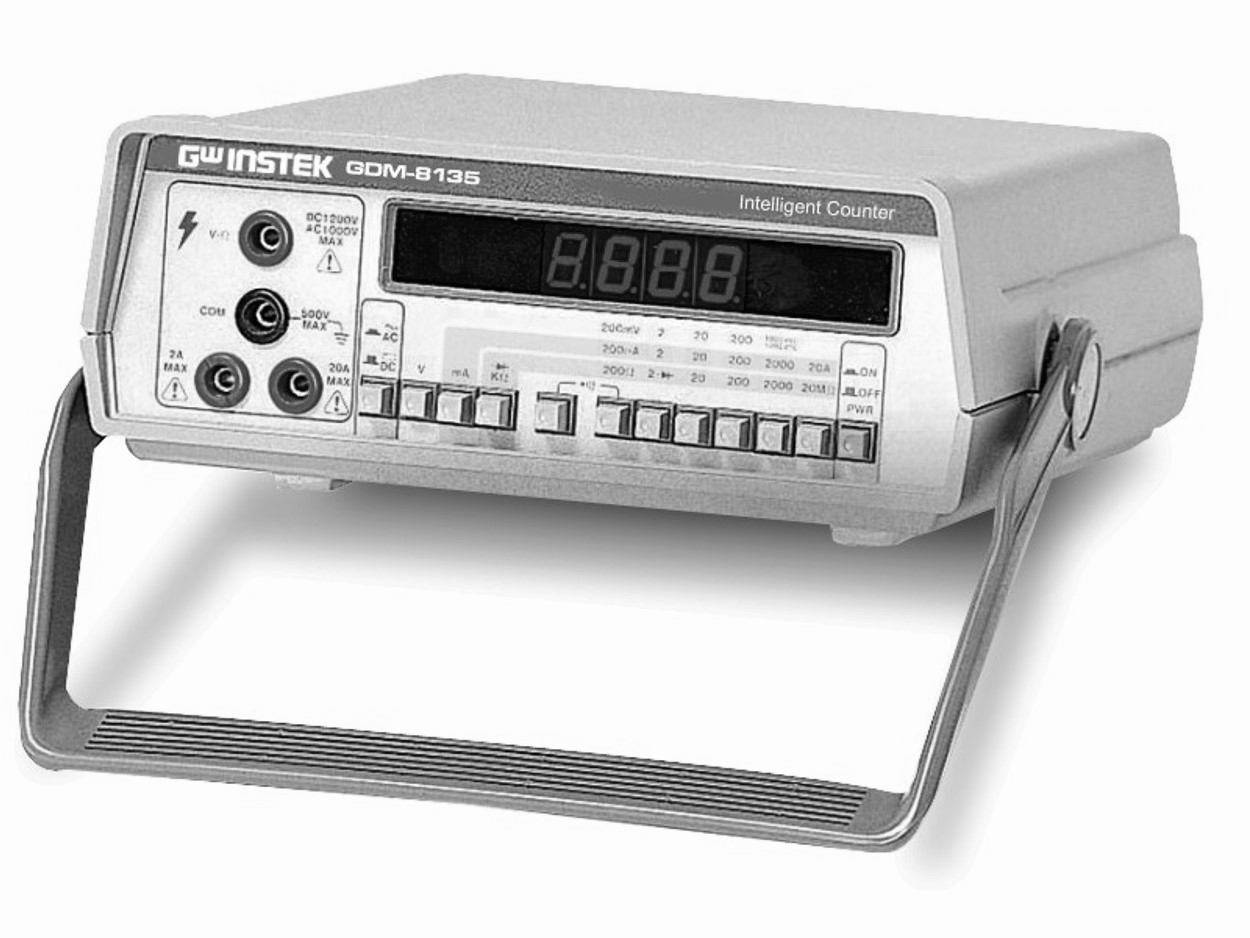 GDM-8135 (단종)
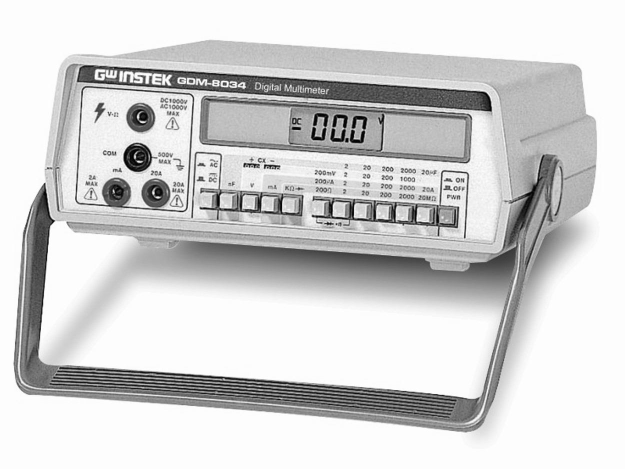 GDM-8034 (단종)
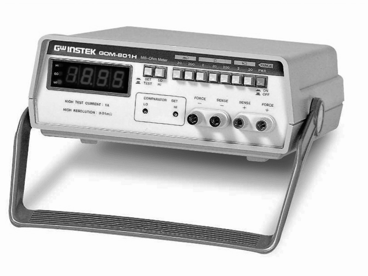 GOM-801H (단종)
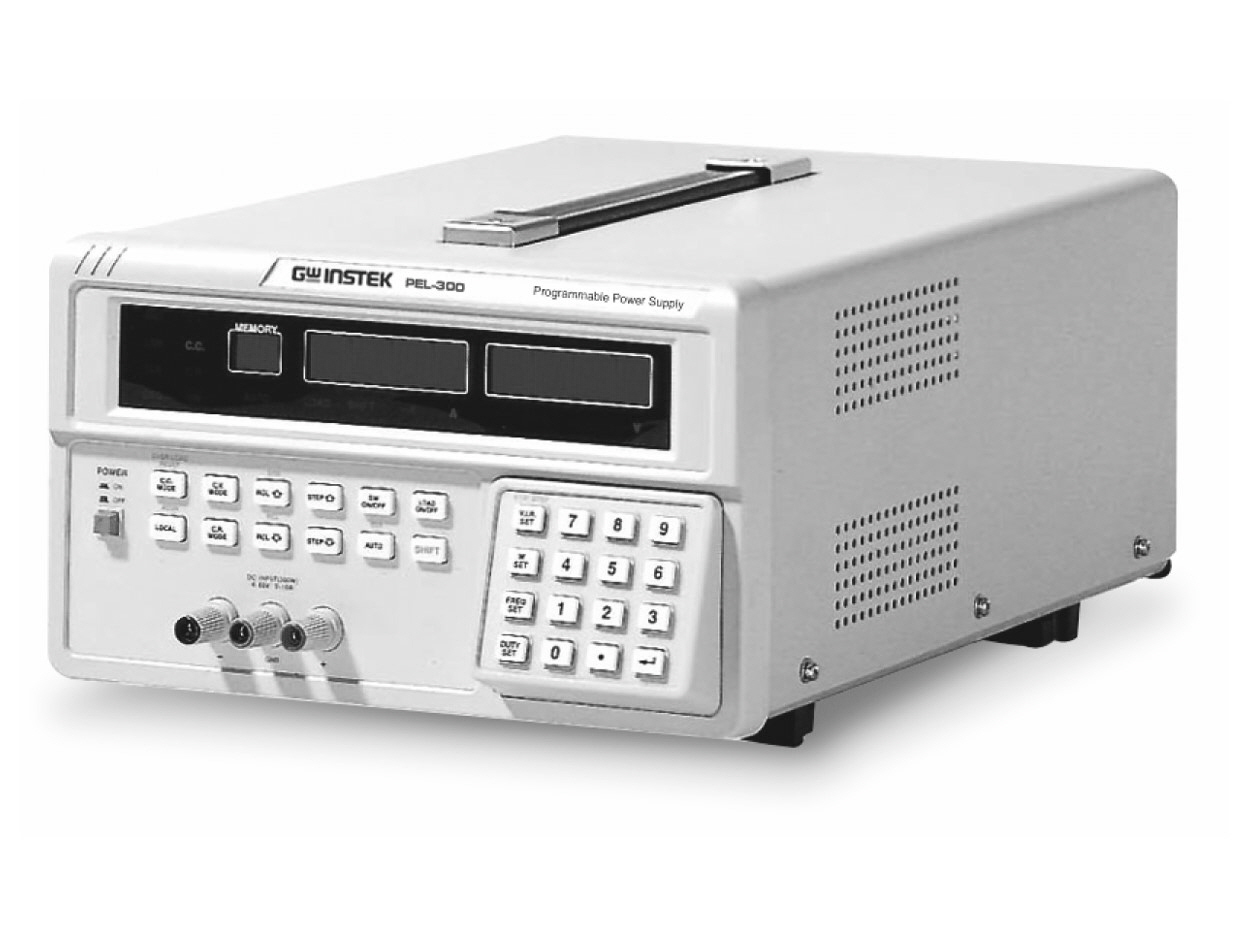 PEL-300 (단종)
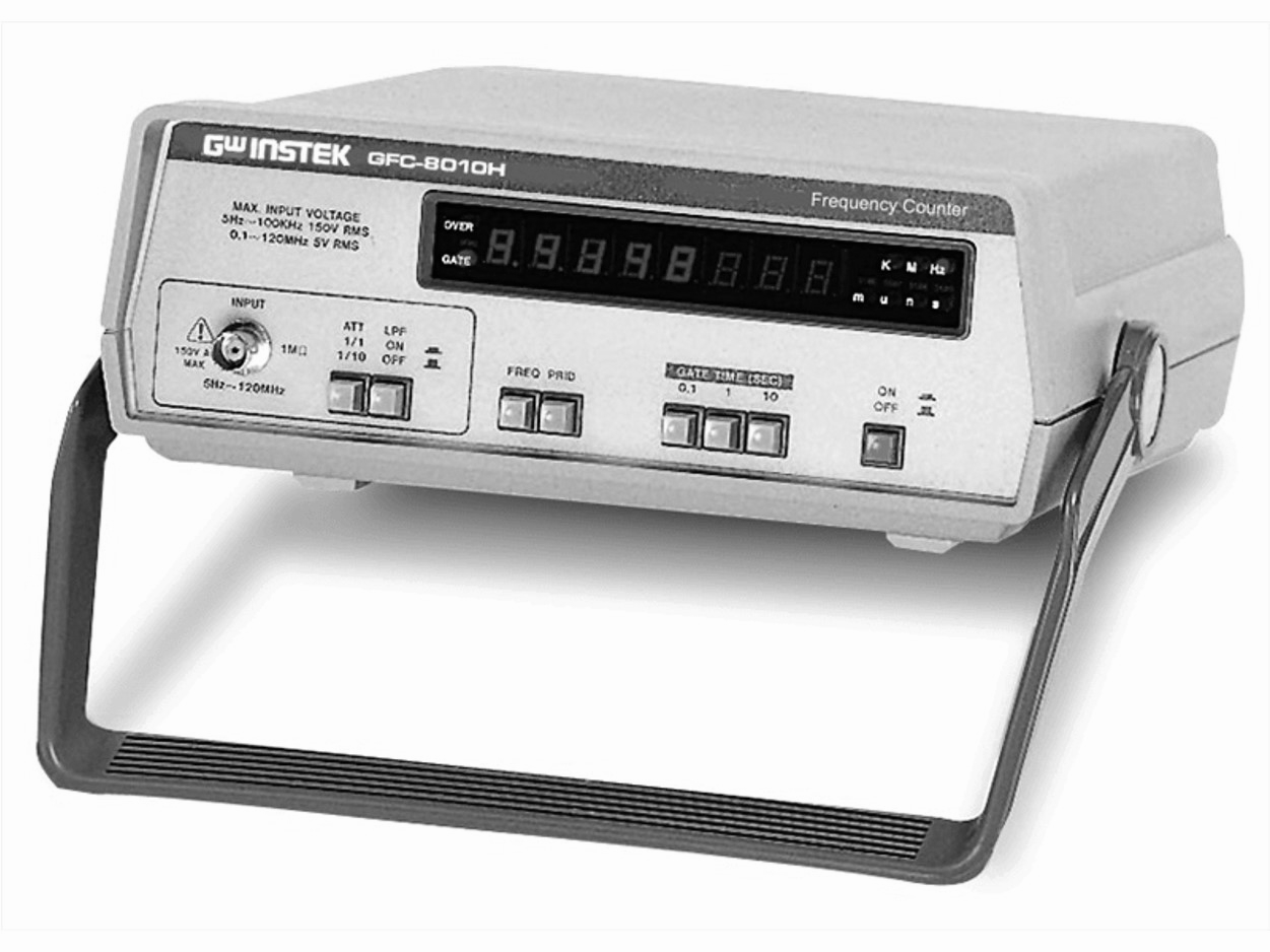 GFC-8010H (단종)
GWINSTEK
02-3439-2208 A/S 신청 및 상담
02-3439-2203/2205/2206gwinstek@gwinstek.co.kr 제품기술문의
 > GWINSTEK > 단종제품
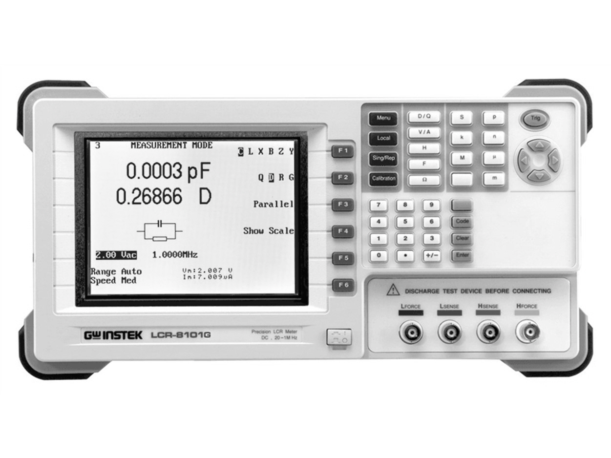
 LCR-8000G 시리즈 (단종)
|
주요 특징 • Wide Test Frequency 20Hz ~ 10/5/1MHz • 0.1% Basic Accuracy & 6 Digits Measurement Resolution • Large LCD Display with Intuitive Interface • Full Measuring Functions with DUT V/I Monitor • PASS/FAIL Function ( abs, % or delta) with Judgment Alarm • DC Resistance Measurement • Multiple Step Mode • Standard RS-232C/GPIB Interface • Optional DC Bias box |
|
The LCR-8000G Series LCR meter, with test frequency up to 10MHz, provides accuracy, versatility and high resolution for a wide range of component measurements, even including DC resistance measurement and Voltage/Current monitoring. The Multi-Step function allows on-screen programming of customized measurement sequence with Pass/Fail indication. Each program includes 30 test steps and each test step can be set with selected parameters and test limits.Under Multi-Step operation, a tedious work routine can be done step by step automatically just at a press of a button. With Graph Mode, LCR-8110G, LCR-8105G and LCR-8101G display the component impedance response either over a wide range of test frequency sweep or over a wide range of test voltage sweep in a graph chart. This gives an analysis result of either impedance vs. frequency or impedance vs. applied voltage all at a glance. GPIB and RS-232C interfaces are available as standard for instrument control andtest result display on the PC. The rich features of LCR-8000G Series easily make your measurement tasks done at a very competitive price. |
|
The Sarter Way to Characterize Component
Friendly Intuitive User Interface
The LCR-8000G Series is designed to perform precision impedance measurements over a wide frequency range of 20Hz~10MHz for LCR-8110G, 20Hz~5MHz for LCR-8105G and 20Hz~1MHz for LCR-8101G.The instrument is capable of measuring 11 different parameters with0.1% basic accuracy, which meets the precision measurement requirements of components and modules used in the RF circuits. The large LCD display with single-layer operation menu of LCR-8000GSeries providesusers with ultimate convenience to plug and play without much learning time. |
|
Pass/Fail Function with Judgment Alarm
In the Pass/Fail test, primary parameter measurement result is compared with user-defined limits and the pass or fail result is then displayed. Three methods, including absolute limit, percentage and delta limit, are available for Hi(high) and Lo(low) limit setting based on the nominal test value. The Pass/Fail test checks whether the parameter measurement result sits within the limits, then display "PASS" for within the limits, or "LO"for lower than the low limit, or "HI" for higher than the high limit. A scale and bar for displaying measurement result is shown at the center of the screen to give a graphical identification, which greatly reduces operator's load in a long time inspection work. This scale and bar also facilitate the adjustment of the variable components. Either Pass or Fail result can be set with a buzzer alarm, which makes component or material sorting easy with sound identification. |
|
Multi Step Mode
The Multi-Step mode is capable of running a series of measurements of a component at a number of user-defined steps in sequence automatically. Total 64 programs can be saved into the non-volatile memory, and each program contains up to 30 test steps. The parameter and Hi/Lo limits can be set respectively for each test step. After a program being properly edited, the instrument can run through all the measurement steps either at a press of the button underthe Manual Trigger selection, or automatically run the program by detecting the connection of a DUT under the Auto Trigger selection. When all the test steps are completed, the screen shows the measurement reading of the parameter being selected for each step with Pass, HI, or LO measurement result. |
|
Graph Mode
The graph function shows the component characteristics in visual manner. Either voltage sweep or frequency sweep can be selected for horizontal scale. Just select the parameter, and set the start/stop voltage or the start/stop frequency of the sweep, LCR-8000G will run through the sequence of measurements and show the results on a graph. This graphical parameter measurement performs the characteristic verification of components and materials over the responseto the changes in AC test frequency or AC test voltage without the need of complex programming of an external controller. When the graph gets out of the vertical range, the LCR-8000G Series can automatically adjust the scale to get full test information. On the graph the marker operation is available for detailed observation. |


|
제품 사양 | ||||
|
|
LCR-8110G |
LCR-8105G |
LCR-8101G | |
|
테스트 주파수 | ||||
|
|
20Hz~10MHz, |
20Hz~5MHz, |
20Hz~1MHz, | |
|
5디지트, ±0.005% |
5디지트, ±0.005% |
5디지트,±0.005% | ||
|
출력 임피던스 | ||||
|
|
100Ω | |||
|
기본 정확도 | ||||
|
|
±0.1% (R, Z, X, G, Y, B, L, C) | |||
|
테스트 속도 | ||||
|
|
AC (>2kHz) |
DC | ||
|
MAX : 75ms |
MAX : 30ms | |||
|
FAST : 150ms |
FAST : 60ms | |||
|
MEDIUM : 450ms |
MEDIUM : 120ms | |||
|
SLOW : 600ms |
SLOW : 900ms | |||
|
테스트 신호 레벨 | ||||
|
|
≤3MHz |
>3MHz | ||
|
테스트 신호 레벨 :10mVrms~2Vrms |
테스트 신호 레벨 : 10mVrms~1Vrms | |||
|
스텝 : 1mV/10mV |
스텝 : 1mV/10mV | |||
|
정확도 : 2%±5mV |
정확도 : 2%±5mV | |||
|
단락 회로 전류 | ||||
|
|
최대 20mA | |||
|
측정 범위 | ||||
|
R, Z, X |
0.1mΩ~100MΩ | |||
|
Rdc |
0.1mΩ~100MΩ | |||
|
G, Y, B |
10nS~1000S | |||
|
L |
0.1nH~100kH | |||
|
C |
0.01pF~1F | |||
|
D |
0.00001~9.9999 | |||
|
Q |
0.1~9999.9 | |||
|
θ |
-180˚~+180˚ | |||
|
측정 매개 변수 | ||||
|
|
임피던스(Z), 위상 각도(θ), 인덕턴스(L), 커패시턴스(C),AC 저항(Rac), 품질 계수(Q), | |||
|
손실 계수 (D), 어드미턴스(Y), 컨덕턴스(G), 리액턴스(X), 서셉턴스(B), DC 저항(Rdc) | ||||
|
직렬/병렬 등가 회로 | ||||
|
|
C+R, C+D, C+Q, L+R, L+Q, L+D | |||
|
직렬 등가 회로 | ||||
|
|
X+R, X+D, X+Q | |||
|
병렬 등가 회로 | ||||
|
|
C+G, B+G, B+D, B+Q, B+R, L+G | |||
|
극 형식 | ||||
|
|
Z+θ, Y+θ | |||
|
일반 | ||||
|
평균 기능 |
1~256 | |||
|
디스플레이 |
320 x 240 도트 매트릭스 LCD 디스플레이 | |||
|
인터페이스 |
RS-232, GPIB | |||
|
AC 입력 전원 |
AC 115V(+10%/-25%), AC 230V (+15%/-14%) (선택가능),50/60Hz | |||
|
치수 및 무게 |
330(W) x 170(H) x 340(D) mm, 약 5kg | |||
|
기본 액세서리 | |
|
사용 설명서 x 1, 전원 코드 x 1, 테스트 리드 LCRC-12 x 1 | |
|
옵션 | |
|
옵션.01 |
DC 바이어스박스 (최대 200V, 2MHz) |
|
GTL-234 |
RS-232 케이블 |
|
GTL-248 |
GPIB 케이블 |
|
GTL-251 |
GPIB-USB-HS (HighSpeed) |
|
GRA-404 |
랙 어댑터패널 (19”, 4U) |